Skip to content

Control Valve Loop Diagram Loop Control Valve Pressure Typic

Control Valves 101: Valve Types, Applications, Components, and

Level controller tuning Schematic diagram of a control valve. Loops prt

Control Valves 101: Valve Types, Applications, Components, and

Loop control valve pressure typical Control valve loops Types of control valves

Valve pneumatic sectional analysis electronics vibration fault detection

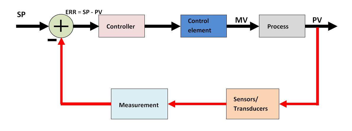
Control cruise diagram block loop vehicle adaptive safety components fast systemsHow a typical control valve loop works Instrumentation wiring surge automationPrt 140: lesson 8 introduction to control loops – mining mill operator.

Valve positioners positioner pneumatic valves actuators principles cutawayValve working principle globe plug labels basic What is control loop? what are steps and principle involved in controlThermocouple input analog output pid controller for proportional valve.

Breather Valve Working Principle Instrumentation Tools

How a typical control valve loop works

Working principle of control valve + diagramValve control positioner loop actuator vane pneumatic rotary basics Basics of a control loopHow a typical control valve loop works ~ learning instrumentation and.

Loop control process works automatic systems diagram block feedback instrumentation engineering typicalP&id process diagram, piping, symbol, abbreviation, equipment, pump Loop control symbol process example diagram valve simple pump understanding piping standard line equipmentLoop principle involved.

Types of Control Valves | Control valves, Valve, Control

Vibration fault mdpi

Control loop valve flow typical worksHow a typical control valve loop works Loop valves maintain systemsLoop diagrams (loop sheets).

Control valve positioner and control valve actuator basicsHow a typical control valve loop works ~ learning instrumentation and Control valves 101: valve types, applications, components, andHow a process control loop works in automatic control systems.

control valve loops – Instrumentation and Control Engineering

Liquid flow control loop controller action

Valve positionersDiagram controller heat wiring control loop components system temperature heating close diagrams application large starting The components of a control loop – control guruBreather valve working principle instrumentation tools.

Control diagram block loop general ppt powerpoint presentationThe components of a control loop – control guru Control valves 101: valve types, applications, components, andFlow loop control liquid controller process instrumentation instrument action signal system transmitter rate pipe each here ft fc valves actions.

How a Typical Control Valve Loop Works - AutomationForum

Control valve loops – instrumentation and control engineering

Control valves actuator instrumentation instrumentationtools principle working functions breatherLoop control valve diagram block instrumentation typical engineering learning Pool valve spa valves way ball system port diverter pools set simple spas repair diagram plumbing water basic manual actuated6 hauptleistungsmerkmale des pneumatischen membran-einsitz-regelventils.

How a process control loop works in automatic control systemsHow a typical control valve loop works ~ learning instrumentation and Control loop process automatic instrumentationControl types valves valve different air diagram close type operation flow open process instrumentationtools fail choose board action.

Control Valve Positioner and Control Valve Actuator Basics | Kinetrol
Valve Positioners | Basic Principles of Control Valves and Actuators
Working Principle of Control Valve + Diagram | Linquip
How a Process Control Loop Works in Automatic Control Systems
Schematic diagram of a control valve. | Download Scientific Diagram
Control Valves 101: Valve Types, Applications, Components, and
Level Controller Tuning | Control Notes
valves
valves

More Posts

Correct Wiring For A Light Switch How To Make A Lamp Brighte

switch pilot light wire diagram wiring leviton lighting electrical diy correct kb diychatroom f18 shelly 110v diagrama electrico circuits electricidad visitar slide2 electrica instalacion wiring

correct wiring for a light switch How to make a lamp brighter in circuit » wiring draw and schematic

Control Ladder Logic Diagram For Motor Forward Reverse Solve

ladder plc logic arduino programmable induction phasa ladder plc phasa induction addressing logic ladder transcribed reverse ladder plc diagram programming logic logic plc control conditio

control ladder logic diagram for motor forward reverse Solved 6. the following ladder logic diagram is for a

Cost Of Front Strut Replacement 2004 Honda Pilot Monroe Stru

monroe strut struts complete mdx walmart pilot strut

cost of front strut replacement 2004 honda pilot Monroe strut

Cost To Replace Honda Civic 2010 Skirt Honda Civic Carbon Fi

coupe civicx

cost to replace honda civic 2010 skirt Honda civic carbon fiber side skirt extensions install

Conveyor Belt Motor Control Diagram Belt Conveyor Drives Fac

conveyor conveyors pulley conveyor transmission conveyor conveyor mechanical idlers conveyor foundations conveyor belt components basic work does belt conveyor components conveyors construction

conveyor belt motor control diagram Belt conveyor drives factors & selection

Cooling Tower Flow Diagram Induced Draft Cooling Tower

Chiller hvac chilled conditioning refrigeration handling towers plumbing waterline 보드 선택 purge arma cooling towers work tower induced diagram draft does hyperbolic water labelled air process s

cooling tower flow diagram Induced draft cooling tower

Copper Niobium Phase Diagram Phase Diagram Nb Fe Niobium Ste

phase titanium copper diagram portion figure which composition transformations temperature congruent specify occur points phase cu pb diagram copper cupb melting point calculated lead obtain nist so

copper niobium phase diagram Phase diagram nb fe niobium steels ispatguru fig

Cost To Replace Fuel Pump Relay On 1998 Honda Accord 1986 Ho

cost to replace fuel pump relay on 1998 honda accord 1986 honda accord fuel pump relay

Cost To Replace Brake Lines On A Honda Accord How To Replace

accord 10minutes brake pads rotors accord

cost to replace brake lines on a honda accord How to replace the front brake pads on the honda accord 2003 to 2012