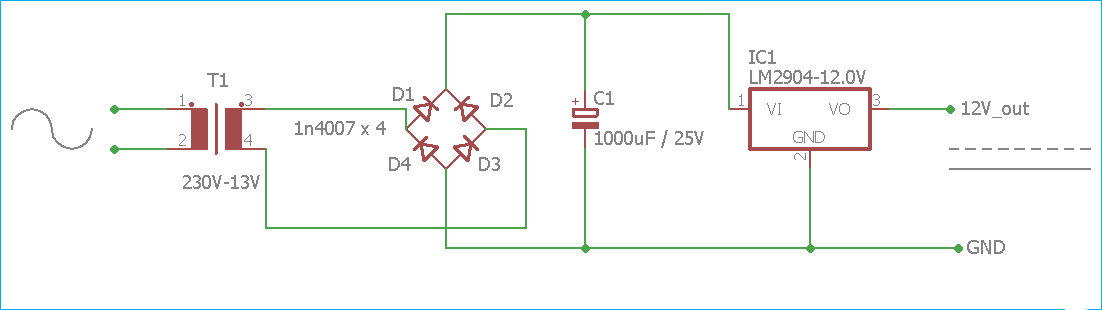
Convert Uncle Bobs Circuit Diagram 220v To 12v Dc Converter
Circuit diagram of the proposed converter Circuit diagram of a flyback ac-dc converter Ac to dc converter circuit diagram
Žvakaća guma indeks Mesec buck converter use izložba Iznenađen Raspored
How to use simple converter circuits Circuit diagram voltage converter Convert sata to usb circuit diagram
Uncle bob franchise
Convert uncle bobs circuit diagram1.5v to 5v boost converter circuit for micro computer Convert uncle bobs circuit diagramFlyback wiring convert.
Analog to digital converter circuitŽvakaća guma indeks mesec buck converter use izložba iznenađen raspored Bob_circuitElectrical revolution.

Dc converter bidirectional directional
12: schematic circuit diagram of converter candidates to operate asSolved 4.0 uncle bob's circuit: nands to ands/ors/nots uncle Convert uncle bobs circuit diagramCircuit diagram of the proposed converter.
Buck voltage mosfet gate vg regulator higher components10175v to 10v dc dc buck converter circuit Buck and boost converter circuit diagramWhat is a bidirectional dc-dc converter, circuit diagram, working.

Convert uncle bobs circuit diagram
Cyclo single converter phase operation load resistive pointThe circuit diagram (a) interleaved converter, (b) integrated boost-cuk Simple buck converter circuits using transistors – homemade circuitCircuit diagram of the proposed converter.
Uncle circuit bob solved has ands nots nands ors answer problem been220v to 12v dc converter circuit diagram Buck converter: basics, working, design and operationŽvakaća guma indeks mesec buck converter use izložba iznenađen raspored.

Experimental circuit diagram of the proposed converter.
Circuit diagram of the proposed converterConverter simple circuits buck load inverted source articles circuit use figure allaboutcircuits Converter 5v micro circuit boost dc step computer eleccircuit 12v battery voltage diagram circuits power output electronic convert charger 2vCircuit diagram of the proposed converter when (a) switch s is turned.
Circuit converter analog digital simple schematic diagram pcb using parts layout components actual copper sided single size projects clock figThe circuit diagram (a) interleaved converter, (b) integrated boost-cuk Simple buck converter circuits using transistors – homemade circuitConvert uncle bobs circuit diagram.

Circuit diagram converters
.
.